With the growing popularity and computing power of the Raspberry Pi single-board computer, many engineers and vintage computer enthusiasts have begun exploring the Pi’s viability as an emulator for legacy minicomputer and mainframe systems. The open nature of the platform’s hardware and software lend itself well to emulation projects, and the board’s GPIO connector allows for a wide variety of interfacing possibilities for peripherals and I/O.
The PiDP-8 kit from Oscar Vermeulen takes advantage of these features by making use of a Raspberry Pi, the SimH emulator software, and a wooden enclosure with LEDs and switches to simulate the DEC PDP-8/I front panel and run the PDP’s OS-8 operating system.
First Impressions
Shipping was quick! The kit found its way from Europe to North America within 3 days, even with a local holiday adding to the turnaround time. The contents were packaged impeccably, with the acrylic front panel covered in protective film to prevent damage. The parts I received were all high-quality, and there were no cosmetic defects or faulty components to be found.
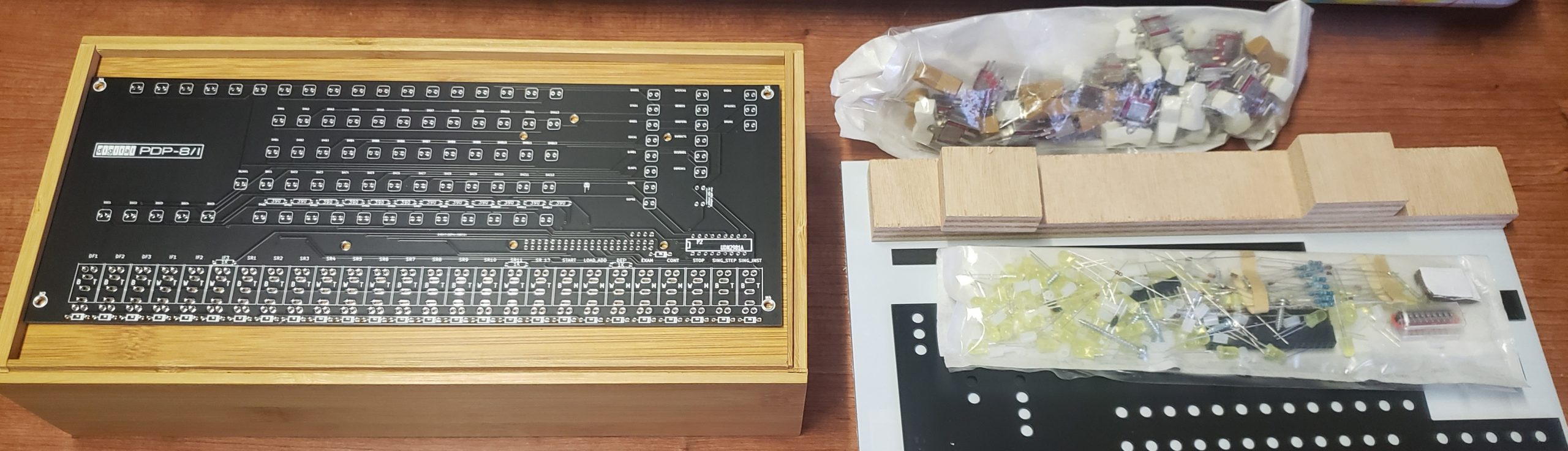
The kit does not include a Pi, but supports all models with the exception of the now-antiquated Pi A and Pi B. I used a spare Pi 3B as I wanted to take advantage of the “glow” effect on the front panel LEDs to simulate the PDP-8/Is incandescent lamps – this feature was not supported on the lower-cost Pi Zero and Zero W.
Preparing the Pi
Material satisfaction aside, it’s vital to note that the PiDP-8’s SimH emulator doesn’t require a front panel to work, and the simulated PDP-8 system can be used in a Linux terminal session on a bare Pi. Initial configuration is a simple process, especially if you have a little experience with the Raspbian setup utility. I used Balena’s Etcher utility on a Windows laptop to write the pre-fab PiDP-8 image to a Micro-SD card, though the software can also be manually installed on an existing Raspbian system if necessary. Once the SD card was prepared, I connected a HDMI monitor and USB keyboard to the Pi, logged in, and changed the default password for the pidp8i user account.
Next, a little work was needed to enable remote access. The sudo dpkg-reconfigure openssh-server command generated SSL keys, and the raspi-config utility was used to enable the SSH service and configure the Pi’s Wi-Fi connection. I also took this opportunity to name the host and edited /boot/config.txt to disable the Pi 3’s persistent undervoltage warnings, as I wasn’t concerned that my power supply would perform poorly with the device given the low power requirements of my application.
Spacers, Switches, Soldering, Satisfaction
With the Pi setup complete, I set it aside and began work on the front panel PCB. Populating the PCB, while not particularly difficult in general, was admittedly a bit of a tedious journey. To put an optimistic spin on the process, less-experienced hobbyists should look at this as a great opportunity to develop basic kit assembly skills by repetition. Bending pins, aligning components, double-checking polarity, soldering, snipping, and testing continuity are all covered along the way.
Diodes and resistors came first – 27 and 15 of each, respectively. I made sure to populate the diodes as instructed by the polarity markings printed on the PCB. I also used a strip of masking tape to help hold these components in place before soldering, as the pins are thin and slip out of the PCB easily.
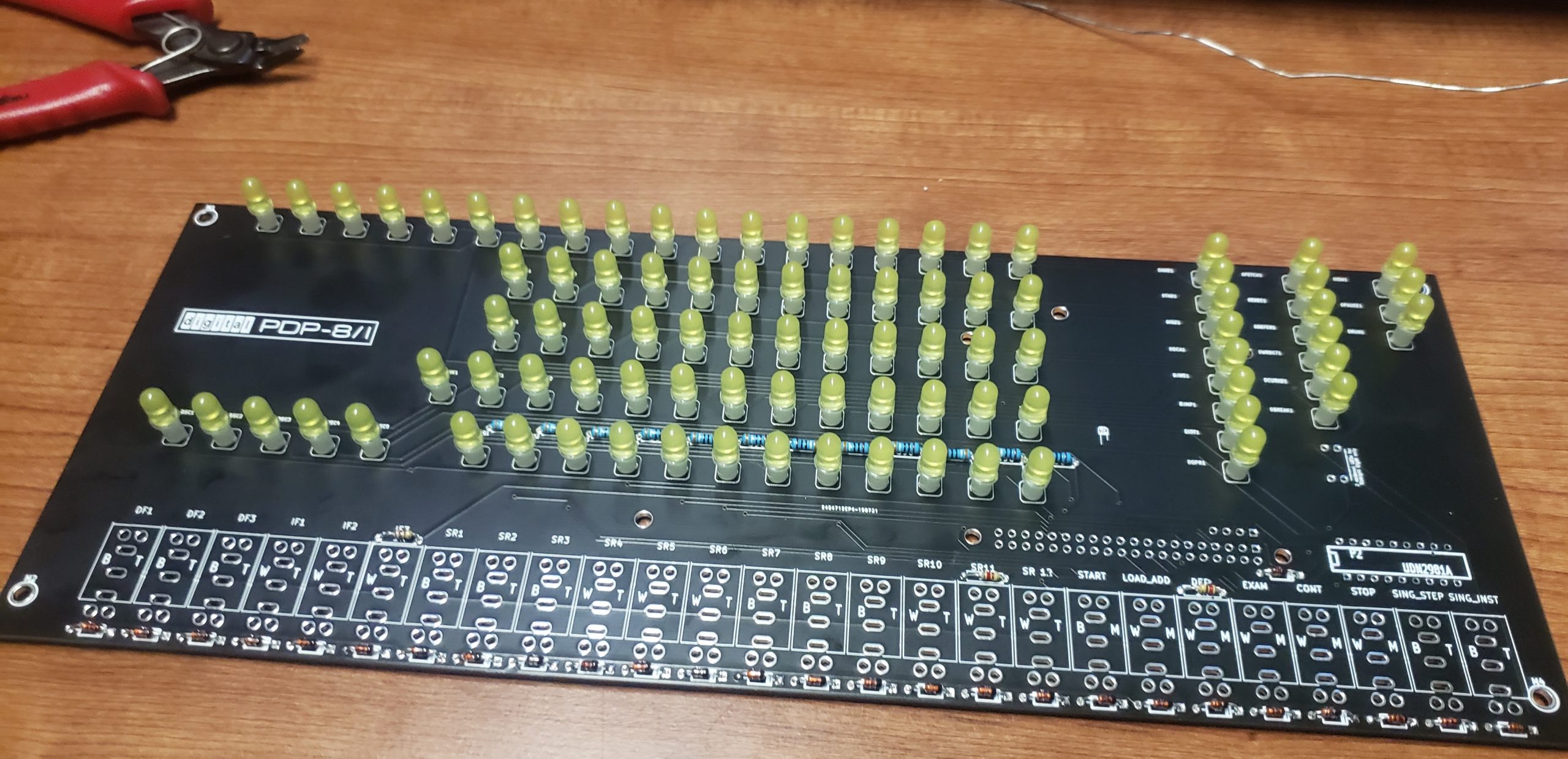
Next, I set about populating the LEDs, which are supported by an assortment of thin plastic spacers. Again, there are a lot of LEDs to solder (89 in total), and care must be taken to ensure that their polarity is correct. The kit includes an LED cover bracket that helped ensure proper spacing and alignment.
I followed up by installing the IC socket and GPIO pin header that connects the Pi and PCB. I’d recommend a little clear tape over the IC socket before soldering the first few pins, similar to that used with the diodes and resistors, as it’ll slip out of the PCB otherwise. The GPIO header was an easy solder job with its thicker pins, despite its smaller pin spacing.
Mounting the Pi was easy enough, though it was a bit difficult to affix the plastic mounting nuts onto their stand-offs. I suspect the threads were a little off, as I did have to use more force than expected.
Time for an LED test! It looked really cool, worked on the first try. and I was overly pleased with myself (don’t worry – my ego will be deflated before long).
Positioning and soldering the switches was by far the most difficult step in assembly. Some of the thicker mounting pins were bent slightly, and I had to straighten most of the switches using a pair of needle-nose pliers before affixing them to the PCB. Though the official instructions recommend soldering only one of the mounting pins and the three leads, I’d recommend soldering all mounting points on the PCB to add stability.
Final Touches
With the board assembled, it was time to connect the Pi and place the kit in its wooden case. I drilled a hole about 1.5cm in diameter through which I threaded the USB Micro-B cable used to power the Pi. I intended to keep my back panel as simple as possible, and this was the only cable used, though there are a multitude of options for Ethernet connectivity, serial console connections, removable connectors/cables, and almost any peripheral one could imagine to interface with the Pi.
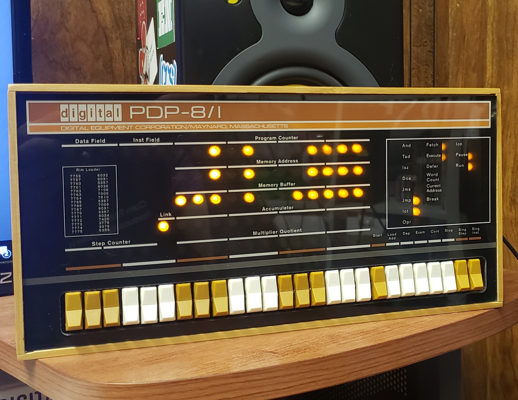
Finally, I affixed a couple of small wooden support blocks to the inside of the case, drilled a few mounting holes, screwed the PCB assembly into the holes, and laid the acrylic front panel into the case. Project complete!
I then realized I had removed the LED cover bracket and forgotten to re-affix it before I finished the build. Oops. Can’t easily remove the front panel to get to it, either. Double oops. Luckily, it’s not an essential component, and the finished product still looks fine without it. I feel this highlights an important caveat of the project – the front panel is tension-fitted to the edges of the case, and it’s very difficult to remove without cosmetic damage once it’s attached. I decided against removing it and elected to leave my assembled kit as-is.
To conclude, this was a fun and functional build that can be used to teach basic kit-building skills, use of the Pi, as well as OS-8 and the PDP-8’s software environment. I won’t go too far into specifics, but there are a lot of fun games and utilities included on the disk images linked from the PiDP-8 site, and I’d highly recommend taking a look. Vermeulen offers a similar PiDP-11 kit that’s a little more pricey than it’s predecessor, but boasts a molded plastic case reflecting the 11’s more “space-age” aesthetic. I’ll be picking this kit up in the near future and hope to put together a similar review and build report once it’s assembled.