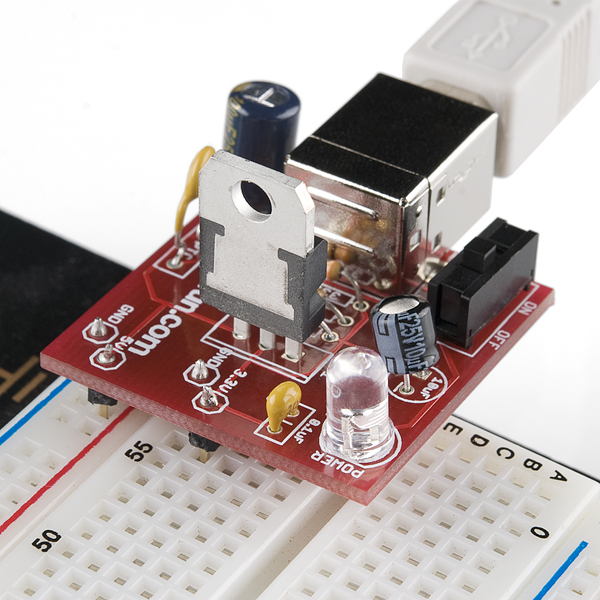
As part of a batch order through Digikey, I recently picked up SparkFun’s USB Breadboard Power Supply kit. This is a small and convenient drop-in module that connects to a breadboard and provides 5V and 3.3V power sources through a USB 2.0 Type-B connector.
Though I had a great time building and using this kit, I also wanted to provide an analysis of the circuit as I feel it could use some documentation for the novice kit builder at which it is targeted. While this is a fairly simple kit to work with, I had trouble finding step-by-step instructions and think it’s important for a kit of this sort to educate the builder while serving a practical purpose.
Here is the schematic provided by SparkFun:
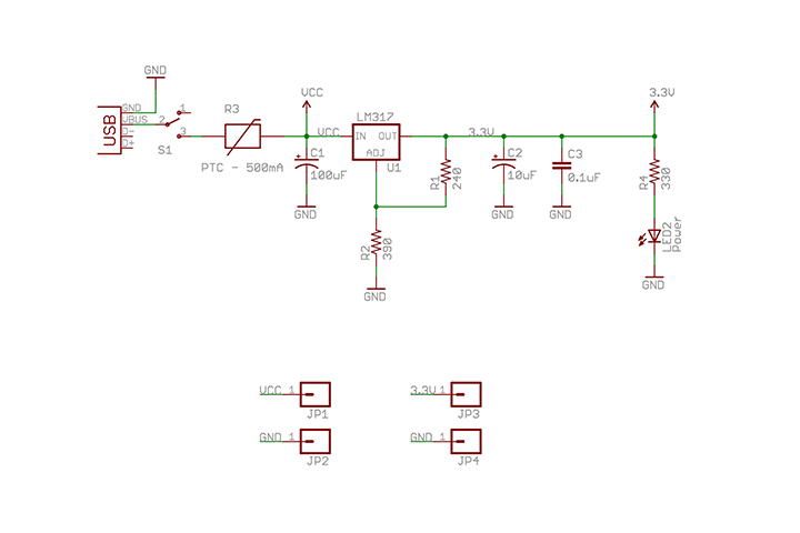
Let’s start at the left side of the image with the USB input. The USB 2.0 standard specifies a power source of 5 volts at 500 milliamps. The 5 volt line is connected through an SPDT-style slide switch. The 2 data pins on the USB plug are left unconnected as they don’t serve a practical purpose in this circuit.
From here, we have two more components between the 5V input line and the LM317 input pin. R3 is a PTC-type resettable fuse – this is similar to a thermistor and serves as a protection mechanism for the circuit. If the amount of current delivered exceeds 500mA, R3 will cut the input line until the overcurrent is removed. Capacitor C1 then serves as a filter to cut high-frequency noise or “ripple” from the input power source.
The circuit centers around the LM317 voltage regulator. This 3-pin IC can output up to 1.5A of current at voltages ranging from 1.2V all the way up to 37V. In our application, it’ll accept the 5V source from the USB connector and output 3.3V from its output pin.
The LM317 uses two resistors labelled R1 and R2 to set the 3.3V output voltage. This voltage is determined by the formula V = 1.25V * (1+R2/R1). Substituting the values of our resistors, this gives us 1.25 * 1+(390/240), which equals 3.28125 volts, which is within a 1% tolerance of our target of 3.3V.
The resulting 3.3V line is then connected to two capacitors. C2 and C3 are 10uF and 0.1uF capacitors respectively and are intended to provide ripple rejection and improve transient response.
Completing the circuit, we have two more branches – one is to our power LED, which is marked as LED2 and is protected by a 330 ohm resistor labelled as R4. Finally, the other branch leads to JP3, which is our final 3.3V output.
I don’t have too much to say about the actual soldering process – it’s fairly straightforward and should be a reasonable challenge for a novice. I would mostly suggest being mindful of the orientations of the polarized components – those are the LM317 voltage regulator, power LED, and electrolytic capacitors. There are two helpful guides for placing the components, those being the schematics, and also the markings on the PCB.
Beyond the more obvious applications of this circuit, we should now also have a good idea of how this type of design could be adapted. For instance, we could swap the USB input with a 5V DC power supply connector, or we could alter the output voltage by replacing our two adjustment resistors with a pair using different resistance values. I suggest taking a look at the LM317 datasheet provided by Texas Instruments, as it provides some additional sample circuits and describes how this power supply could easily be converted to a battery charger with the addition of a shutoff transistor.
To sum up, this is a great starter kit with practical value that can be had for under 20 dollars. In my case, I already have a computer with a USB port sitting on my bench, so I no longer need to use up an AC outlet for a wall wart power supply. It’s great for anyone needing a quick 5V or 3.3V power source to their breadboard, and is an excellent way to learn about basic power supply design and the use of the LM317.
You can purchase the kit here – https://www.sparkfun.com/products/8376